
MATLAB To HDL Conversion

  Hello Dear Reader,

Here in this post, I will give an idea about how HLS(High-Level Synthesis) works. Here This kind of higher-level language to HDL conversion facility is provided by one of the famous software MATLAB. Here I have implemented a full-adder logic functionality to test the steps. So Let's see how it work.

Steps:

1) Open MATLAB

2) Write a function that you want to convert to VHDL


3) Go to Apps and search for HDL Coder

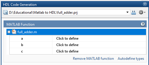
4) Open HDL Coder and make a new project


5) Add MATLAB function file


6) Click on Workflow Advisor


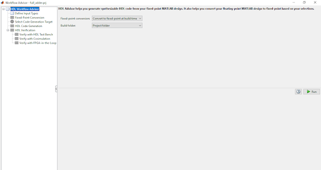
7) Select Convert to fixed-point at build time because double operation is not suitable for FPGA


8) Define input types


9) Go to Fixed-point conversion and define Static Min and Static Max
10) Go to Data collection and Compute Derived Ranges


11) Select Code Generation Target


12) HDL Code Generation
   Select VHDL as an HDL format for RTL conversion. And the last step is to press the run menu which is situated middle of the right side.


13) VHDL Code
   Here below is the VHDL code which is obtained from the above steps which say our steps are successfully implemented.

LIBRARY IEEE;
USE IEEE.std_logic_1164.ALL;
USE IEEE.numeric_std.ALL;

ENTITY full_adder_fixpt IS
  PORT( a                                 :   IN    std_logic;
        b                                 :   IN    std_logic;
        c                                 :   IN    std_logic;
        carry                             :   OUT   std_logic;
        sum                               :   OUT   std_logic
        );
END full_adder_fixpt;


ARCHITECTURE rtl OF full_adder_fixpt IS

BEGIN
  --HDL code generation from MATLAB function: full_adder_fixpt
  --%%%%%%%%%%%%%%%%%%%%%%%%%%%%%%%%%%%%%%%%%%%%%%%%%%%%%%%%%%%%%%%%%%%%%%%%%%%
  --                                                                          %
  --           Generated by MATLAB 9.4 and Fixed-Point Designer 6.1           %
  --                                                                          %
  --%%%%%%%%%%%%%%%%%%%%%%%%%%%%%%%%%%%%%%%%%%%%%%%%%%%%%%%%%%%%%%%%%%%%%%%%%%%
  sum <= ((((( NOT a) AND ( NOT b)) AND c) OR ((( NOT a) AND b) AND ( NOT c))) OR ((a AND ( NOT b)) AND ( NOT c))) OR ((a AND b) AND c);
  carry <= ((a AND b) OR (b AND c)) OR (a AND c);

END rtl;


Comments

  1. Superb easy explanation for this awaiting topic.

    ReplyDelete
  2. Completed sir this steps best learning thanks for your efforts.

    ReplyDelete
  3. First ever I found this solution

    ReplyDelete

Post a Comment

Popular posts from this blog

Design Engineer at Infineon Bangalore

  Hello Dear Readers, Currently at Infineon Bangalore vacancy for the Design Engineer role. Design analog and mixed-signal modules in CMOS and Smart PowerTechnologies, with a particular focus on achieving high-efficiency power conversion for applications using GaN devices; In your new role you will: Design analog and mixed-signal modules  in CMOS and Smart PowerTechnologies, with a particular focus on achieving high-efficiency power conversion for applications using GaN devices; Design and verify pre-silicon analog/mixed-signal integrated circuit blocks, including incorporating features for testing and quality assurance, and providing support for top-level integration; Assist in defining the requirements  for analog and mixed-signal blocks,aligning them with IP Module architecture, and ensuring compliance with requirements through documentation; Estimate effort and planning design work packages to meet project milestones; Provide essential support to physical design ...

Engineer II - Analog Design Engineering at Microchip

Hello Dear Readers,   Currently at Microchip  vacancy for Engineer II - Analog Design Engineering role. Job Description: The Mixed Signal Development Group is responsible for delivering analog, digital and mixed-signal IP to divisions within Microchip. We work with leading edge CMOS processes to produce analog integrated circuits for wireline applications. From 112Gb/s+ SERDES to high-speed FEC engines, we enable technology that allows Microchip’s products to interface to the outside world.  Job Descriptions: As a member of the Mixed-Signal Development Group, the candidate will be supervised by a team leader/manager, and be engaged in the design of SERDES/DSP blocks, and other high-speed Digital Signal Processing blocks. This will involve taking a design from initial concept to production form. Throughout you will be mentored and coached by experienced engineers and be exposed to Microchip's Best-In-Class engineering practices. Job Responsibilities: Ramping up o...

Tutorial on EasyEDA desktop software for PCB and schematic design

In this article, I am going to write a tutorial on how to use EasyEDA desktop application for creating a schematic and for PCB design. One of best advantage of this software is that you can create design offline and can automatically synchronize your design with your online EasyEDA account.  It can be used for circuits simulation, PCB deign and electronics circuits design. You can download EasyEDA desktop application by clicking on following link and it will work on windows 7 or its greater version. They are also releasing soon offline application OSX and Linux users. So keep visiting their website for more information.                                                    https://easyeda.com/page/download So let’s start and see how to design a schematic and PCB using EasyEDA offline desktop application. So first of all lets see how to create a schema...