
different types of wave propagation

(a) Ground wave propagation:
The type of propagation in which radio waves propagate from transmitting antenna to receiving antenna following the surface of the earth is called ground wave propagation.
Electromagnetic waves which are vertically polarised can travel by this mode.
The intensity at the signal falls with the distance as radiowaves induce current in the ground over which they pass. As the wave propagate, the corresponding angle of tilt goes on increasing after a certain time the wave dies out.
Frequency at which ground waves travel is upto 1500 KHZ.
c = f.λ
wavelength, λ = 200m
Used for local broadcasting, ship communication etc.
b) Sky wave propagation:
The propagation of Radiowaves from tranmitting antenna to receiving antenna via reflection from the ionosphere is called sky wave propagation.
The ionosphere region consists of ions which extends from a height of 60km to 300 km.
As we go higher in the ionosphere, there is an increase in the free electron density consequently there is decrease in the Refractive Index (μ).
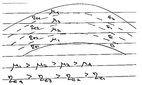
Thus, as radiowave travel up in the ionosphere it travels from denser medium to rarer medium. It continuously bends from its path till it suffers total internal reflection to reach back to the Earth.
c) Space wave propogation:
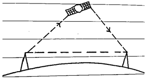
Space wave propagation can be achieved in the following 2 ways:
1) LOS Communication
2) Satellite Communication
Consider a TV antenna OP of height h. The transmitted signal cannot be received beyond points  and 
OR1 and OR2 are maximum distance from the antenna.
let OR1=OR2=d
from PCR1

Comments

Post a Comment

Popular posts from this blog

Tutorial on EasyEDA desktop software for PCB and schematic design

In this article, I am going to write a tutorial on how to use EasyEDA desktop application for creating a schematic and for PCB design. One of best advantage of this software is that you can create design offline and can automatically synchronize your design with your online EasyEDA account.  It can be used for circuits simulation, PCB deign and electronics circuits design. You can download EasyEDA desktop application by clicking on following link and it will work on windows 7 or its greater version. They are also releasing soon offline application OSX and Linux users. So keep visiting their website for more information.                                                    https://easyeda.com/page/download So let’s start and see how to design a schematic and PCB using EasyEDA offline desktop application. So first of all lets see how to create a schema...

What is Solar System Components & Installation Guide

Hello Dear Reader, Here in this post, I will give an idea about installation cost analysis of Solar PV System. I hope you read this post regarding the calculation of solar PV system  so in this post I have given an approximate cost analysis of the different solar system installations.  What is Solar System Components Solar systems are made up of solar panels (modules), a mounting system, and a solar inverter with computerised controller. Solar panels produce DC electricity from sunlight. Then the inverter converts the generated electricity into AC, so that it can be used in the household. The computerised controller manages the solar system and ensures optimal performance. If you want a battery backup system or an off-the-grid solar system, a battery is required. What is a Solar Energy System? Solar Energy System consists of 4 main components that decide the working of a solar energy system. Solar Panel Solar Inverter Solar Battery Panel Stand, and Solar Panel Installation...

CMOS OPAMP Design Using LTspice

  Hello Dear Reader, Here in this post, I will give an idea about how CMOS OPAMP designing using 180nm technology node and using LTspice. from that opamp I have design switched capacitor integrator. Design Specifications: Here Design specification may be changed according to the application here my target is to design an active lowpass filter so I have chosen an opamp integrator so in the below I have explained how to design an opamp as well as an integrator in a 180nm technology node in LTspice. So let's start design First, we need a technology parameter file so that the file we can insert in the LTspice, in my example it is 180nm so mostly it is available from the  http://ptm.asu.edu/latest.html  and you make one text file using notepad or whatever is fit on your own. Then go to the LTspice and new schematic and then you see .op on the right most upper side click on it and give your text file path after .include  as shown in the below images.  Now first of all...